|
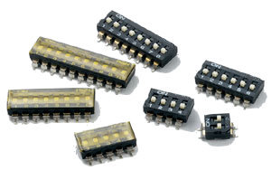
RM / RMR Series
|
 |
|
RM series
|
|
RMR series
|
|
-
RM series (raised actuator) and RMR series (recessed actuator) available for different purposes.
-
Low contact resistance, and self-clean on contact area.
-
Gold plated electrical contact and terminal plating by gold give excellent results when soldering.
-
Double contacts offer high reliability.
-
All materials are UL94V-0 grade fire retardant plastics.
|
|
ITEM |
Description |
Materials |
Treatment |
|
1 |
Actuator |
UL94V-0 Nylon |
Molded white |
|
2 |
Cover |
UL94V-0 Nylon |
Molded black |
|
3 |
Base |
UL94V-0 Nylon |
Molded black |
|
4 |
Contact |
Beryllium Copper
|
Gold plated at contact area |
|
5 |
Terminal |
Brass |
Gold plated at contact area
and gold plating at terminal |
|
PROD NO. |
NO. OF POS |
DIM A |
|
|
RM/RMR-01 |
01 |
3.48 |
0.137 |
|
RM/RMR-02 |
02 |
6.02 |
0.237 |
|
RM/RMR-03 |
03 |
8.56 |
0.337 |
|
RM/RMR-04 |
04 |
11.1 |
0.437 |
|
RM/RMR-05 |
05 |
13.64 |
0.537 |
|
RM/RMR-06 |
06 |
16.18 |
0.637 |
|
RM/RMR-07 |
07 |
18.72 |
0.737 |
|
RM/RMR-08 |
08 |
21.26 |
0.837 |
|
RM/RMR-09 |
09 |
23.8 |
0.937 |
|
RM/RMR-10 |
10 |
26.34 |
1.037 |
|
RM/RMR-12 |
12 |
31.42 |
1.237 |
| Example: |
RMR-08G-T is a surface mounting Type Dip Switch, Recessed Actuator 8 position, with, top tape sealed.
|
| PACKING |
All DIP switches are shipped in standard IC tubes or Tape & Reel Package with all poles in the "OFF" position. |
|
PART NO.
|
NO. OF POS |
A |
B |
C |
Q'TY/REEL
|
|
RMR-02G-T-R |
02 |
6.50 |
5.5 |
16 |
800 pcs |
|
RMR-03G-T-R |
03 |
9.00 |
7.5 |
16 |
800 pcs |
|
RMR-04G-T-R |
04 |
11.50 |
11.5 |
24 |
800 pcs |
|
RMR-05G-T-R |
05 |
14.10 |
11.5 |
24 |
800 pcs |
|
RMR-06G-T-R |
06 |
16.60 |
14.2 |
24 |
800 pcs |
|
RMR-07G-T-R |
07 |
19.10 |
14.2 |
32 |
800 pcs |
|
RMR-08G-T-R |
08 |
21.70 |
14.2 |
32 |
800 pcs |
|
RMR-09G-T-R |
09 |
24.20 |
20.2 |
44 |
800 pcs |
|
RMR-10G-T-R |
10 |
26.70 |
20.2 |
44 |
800 pcs |
|
RMR-12G-T-R |
12 |
31.90 |
20.2 |
44 |
800 pcs |
|
 |
Tape & reel packing (Per EIA standards)
For packing details, please refer to pages 13 |
Electrical life: 2000 operation cycles per switch 24VDC, 25mA.
Non-Switching Rating: 100mA, 50 VDC
Switching Rating: 25mA, 24VCD. |
| Contact resistance: |
(a) 50mΩ max. at initial
(b) 100mΩ max. after life test. |
Insulation resistance: 100MΩ min. (at 500VDC)
Dielectric Strength: 500VAC/1 minute.
Capacitance: 5pF max.
Circuit: Single pole single throw |
Mechanical life: 2000 operations per cycle switch
Operation Force: 600gf max.
Stroke: 0.9mm
Operation Temp: -25° C to +70° C
Storage Temp: -40° C to +85° C |
| Vibration Test: |
MIL-STD-202F METHOD 201A
Frequency: 10-55-10Hz/1 min
Directions: X, Y, Z, three mutually
perpendicular directions.
Time: 2 hours each direction.
High reliability. |
| Shock Test: |
MIL-STD-202F METHOD 213B.
CONDITION A
GRAVITY: 50G (peak value), 11 m/sec.
Direction and times: 6 sides and three times in
each direction. High reliability. |
| SOLDERING AND CLEANING PROCESSES |
| For best results, please follow these recommendations: Keep all switch contacts in their "OFF" position for all operations. |
| Soldering: |
vapor phase & IR-reflow soldering can be applied. |
| CLEANING PROCESS:
|
Flux clean using force rinse, high agitation or triple bath cleaning method. Freon TF or TE give excellent results. When vapor methods are used, do not subject the switch to solvents at temperatures above 125
F (51° C). |
| Reflow Temperature Profile. (reference) |
|